
AVIONICS EQUIPMENT REPAIR AND OVERHAUL SERVICES
AVIONICS EQUIPMENT REPAIR AND OVERHAUL SERVICES
AVIONICS EQUIPMENT REPAIR AND OVERHAUL SERVICESAVIONICS EQUIPMENT REPAIR AND OVERHAUL SERVICESAVIONICS EQUIPMENT REPAIR AND OVERHAUL SERVICESReliable overhaul repair services for:
AN/APN-209(V)
RT-5000
AN/APN-171(V)
AN/APN-194(V)
AN/PRC-90-2
AN/ASN-128
Zero Adjustment
AVIONICS EQUIPMENT REPAIR AND OVERHAUL SERVICES
AVIONICS EQUIPMENT REPAIR AND OVERHAUL SERVICES
AVIONICS EQUIPMENT REPAIR AND OVERHAUL SERVICESAVIONICS EQUIPMENT REPAIR AND OVERHAUL SERVICESAVIONICS EQUIPMENT REPAIR AND OVERHAUL SERVICESReliable overhaul repair services for:
AN/APN-209(V)
RT-5000
AN/APN-171(V)
AN/APN-194(V)
AN/PRC-90-2
AN/ASN-128
Zero Adjustment
Components Serviced
APN-209
APN-209
APN-209
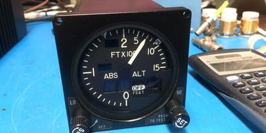
The APN-209 system is a pulse-type radar altimeter that utilizes two antennas to transmit and receive signals.
RT-5000
APN-209
APN-209
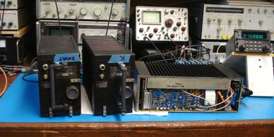
The RT-5000 transceiver with C-5000 control is a communication system providing wide frequency coverage.
APN-171
APN-209
APN-171
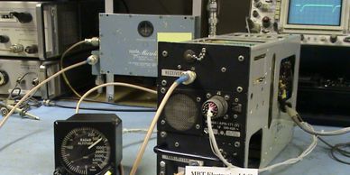
The AN/APN171(V) radar altimeter system consists of a remote RT unit, two antennas, and one or more panel mounted indicators.
APN-194
PRC-90-2
APN-171
The AN/APN-194(V) radar altimeter system consists of a remotely mounted RT unit, two antennas, and one or more indicators and an interference blanker.
PRC-90-2
PRC-90-2
PRC-90-2
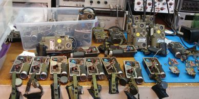
The PRC-90-2 is a military pilot's personal emergency beacon and communication radio.
ASN-128
PRC-90-2
PRC-90-2
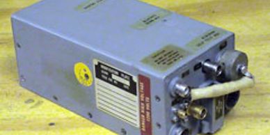
The RT-1193/ASN-128 and RT-1193A/ASN-128 system uses Doppler radar as its primary sensor.
Zero Adjustment
Zero Adjustment
Zero Adjustment
During maintenance, the radar altimeter is adjusted to read zero feet with a very short RF path between transmitter and receiver antennas.